From CAD to First Flight: The Aircraft Development Journey
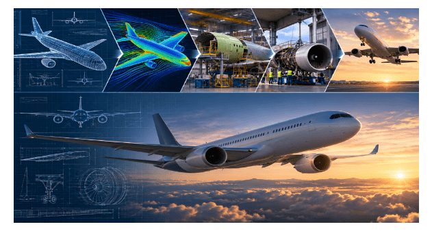
Figure 9.1: The end-to-end design trajectory: translating digital parametric CAD topology into physical, wing-borne flight dynamics.
1. The Conception Phase: Requirements Definition and Conceptual Sizing
Every new aircraft begins not with a computer model or a sheet of metal, but with a statement of operational requirements. In aerospace engineering, before drawing a single aerodynamic curve, we must define the vehicle's mission envelope: what payload must it carry, across what design range, at what cruising speed and altitude, and under what regulatory certification framework? Whether designing a single-engine utility airplane, an electric vertical take-off and landing transport, or a transcontinental transport category aircraft, this operational baseline forms the technical compass for the entire program.
The engineering journey commences with conceptual sizing. Here, classical aeronautical estimation methods, historical statistical regressions, and mission-segment energy balance calculations converge. We estimate the maximum gross take-off weight (MTOW), empty weight fractions, required fuel or battery storage capacity, wing surface area, and propulsion requirements. The Breguet range equation serves as a governing constraint during these preliminary calculations: range is fundamentally tied to aerodynamic efficiency (the lift-to-drag ratio, L/D), specific fuel consumption or battery energy density, and structural weight fractions. During conceptual sizing, hundreds of trade studies are conducted across key wing configurations - such as conventional cantilever layouts versus closed-loop box wings - to determine the baseline architecture that fulfills the required mission profile with minimal weight and drag penalties.
2. Digital Architecture: Advanced CAD and Aerodynamic Optimization
Once the configuration architecture is locked, the program shifts from spreadsheets to Computer-Aided Design (CAD) and Computational Fluid Dynamics (CFD). Modern aerospace development relies heavily on digital continuity, where parametric 3D models serve as the single source of truth for all engineering disciplines. Every structural bulkhead, rib, skin panel, flight control actuator, and avionics shelf is modeled within a unified digital assembly.
Aerodynamic surface definition demands exceptional precision. Engineers generate lofted aerodynamic surfaces incorporating carefully tuned airfoil profiles designed for the vehicle's target Reynolds number and Mach regime. High-fidelity CFD solvers run thousands of simulations across the flight envelope, modeling viscous boundary layers, pressure distributions, flow separation margins, and vortex dynamics. In complex airframes, such as tandem wings or distributed electric propulsion systems, CFD captures the unsteady aerodynamic interactions between rotor downwash columns, wing boundaries, and fuselage wakes. Concurrently, internal structural layouts take shape within CAD. Engineers establish primary load paths, placing primary spars to absorb bending moments, shear webs to resist aerodynamic shear, and ribs to maintain airfoil camber profiles under load. Finite Element Analysis (FEA) meshes are mapped directly from CAD surface models to analyze internal stress concentrations, buckling tendencies, and torsional deformations, allowing structural engineers to optimize airframe mass before physical fabrication begins.
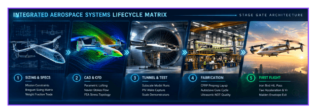
Figure 9.2: The multidisciplinary aerospace engineering pipeline from concept to flight trial clearance.
3. Physical Verification: Wind Tunnel Testing and Subscale Prototyping
Despite supercomputing clusters, computational fluid mechanics remains an approximation. Subscale wind tunnel testing remains a mandatory milestone to validate analytical models and discover complex flow phenomena that digital simulations may underpredict. Engineers fabricate geometrically scaled wind tunnel models embedded with hundreds of pressure taps and mounted to multi-axis strain-gauge internal balances to measure true lift, drag, and moments across angles of attack and sideslip. Specialized flow visualization techniques illuminate boundary layer transitions and turbulent wake interactions. Subscale demonstrators allow flight control teams to test control laws and autopilot algorithms in the real atmosphere at a fraction of full-scale development risk.
4. Airframe Manufacturing: From Raw Composites to Final Assembly
When digital validation is complete, the aircraft transitions into the physical manufacturing environment. Carbon-fiber reinforced polymers (CFRP) serve as the material of choice for primary airframe structures due to their high strength-to-weight and stiffness-to-weight ratios. Precision-cut carbon plies are layered inside master tooling molds, vacuum-bagged, and cured in autoclaves under monitored temperature and pressure cycles. Non-destructive testing (NDT) via ultrasonic scanning ensures zero internal delaminations or voids before major structural modules are laser-aligned and permanently mated.
Lifecycle Stage | Primary Engineering Deliverable | Failure Mode Prevention & Safety Gate |
Loft Definition | Parametric outer-mold-line (OML) CAD geometry | Shock stall mitigation and boundary layer separation control |
FEA Optimization | Monocoque and internal spar structural schedule | Compressive spar-cap buckling and shear-web collapse |
Composite Layup | Autoclaved carbon-fiber skin and bulkhead subassemblies | Matrix porosity, resin starvation, and ply wrinkles |
Iron Bird Testing | Full-scale Fly-By-Wire hardware-in-the-loop validation | Actuator stalls, bus packet dropouts, and trim runaways |
Taxi & Rotation | Ground stability, rudder authority, and rotation response | Gear shimmy, dynamic brake fade, and pitch over-rotation |
5. Systems Integration, the "Iron Bird", and Maiden Flight
An assembled airframe is merely a passive structural shell; its operational life depends on mechanical, electrical, and avionic subsystems. Long before rollout, critical systems undergo thousands of hours of ground testing on hardware-in-the-loop (HIL) test rigs, known as the "Iron Bird". Flight control computers, Fly-By-Wire actuators, and power distribution systems are driven against mechanical loads replicating in-flight dynamic pressures. Failure injections verify that single-point failures isolate automatically without compromising control authority.
Following ground vibration and proof-load testing, the aircraft advances to taxi runs, rotation checks, and finally its Maiden Flight. Guided by real-time telemetry streams monitoring flutter, control-loop latencies, and thermal states, the test pilot evaluates basic handling qualities and stability corridors. Touchdown marks the conclusion of development and unlocks the extensive envelope-expansion campaign required to certify the aircraft for safe operational service.
KEY ENGINEERING TAKEAWAY - The journey from CAD to first flight is an unbroken chain of digital and physical verification: conceptual sizing establishes feasibility, high-fidelity CFD and FEA optimize the geometry, the Iron Bird validates flight controls, and disciplined flight testing proves operational safety. |