Prototype Development Explained
1. Introduction to Aeronautical Prototyping
In aerospace engineering, building a prototype is not merely an exercise in creating a sample product; it is the fundamental bridge that connects computational theory to the unforgiving physics of the atmosphere. Aerodynamics, structural dynamics, thermal dissipation, and fly-by-wire automation all intersect simultaneously on a flying vehicle. While computational fluid dynamics (CFD) and finite element analysis (FEA) allow engineers to simulate complex behaviors on digital workstations, the real atmosphere contains unmodeled edge cases, non-linear boundary layer transitions, structural vibration modes, and dynamic environmental turbulence that software simulations cannot fully predict.
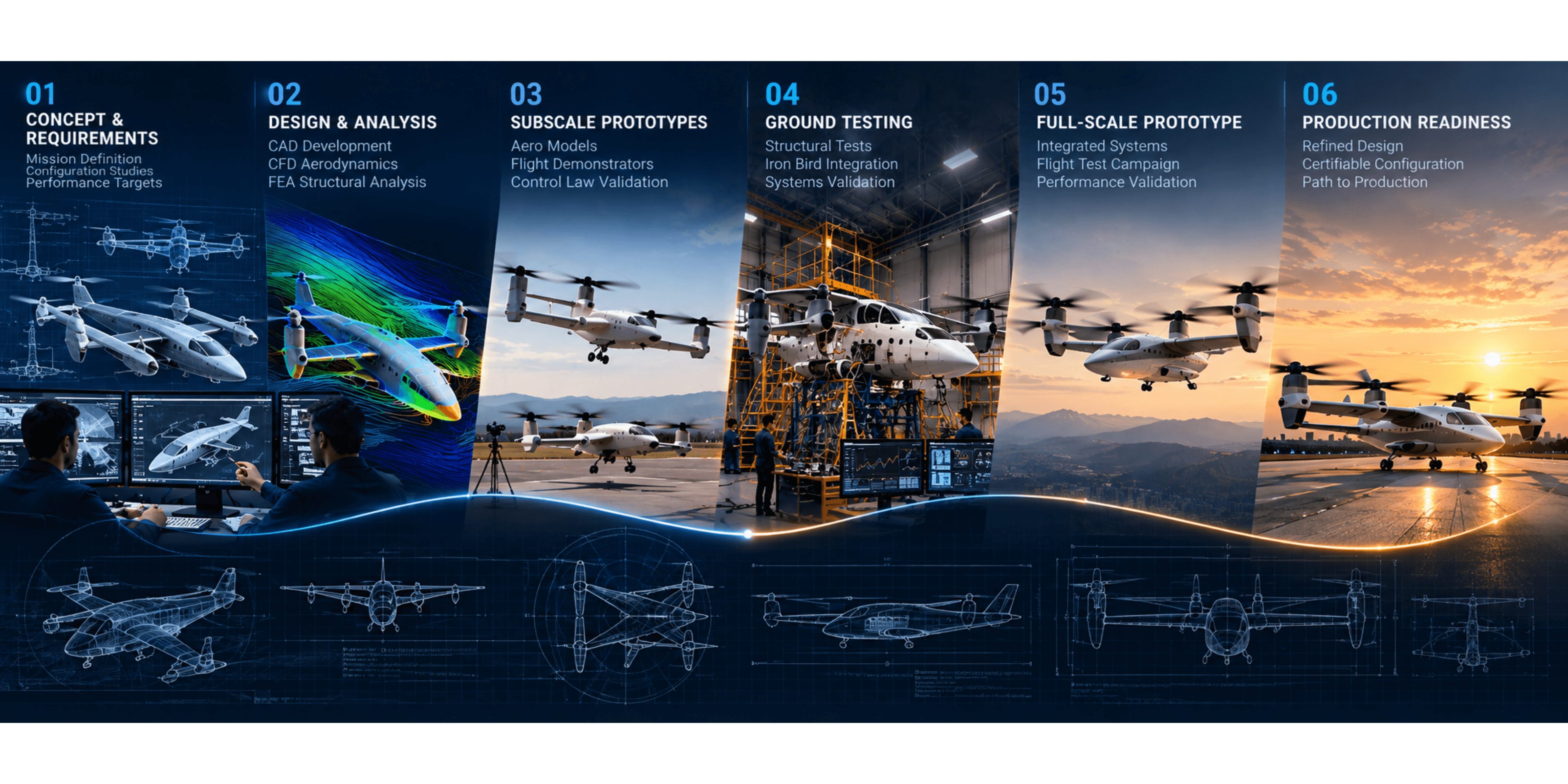
Prototyping serves as an iterative risk-reduction mechanism. It allows development teams to fail early, cheaply, and safely on subscale test articles and ground-based rigs long before embarking on the immense capital expenditure required to tool up and manufacture full-scale, certified commercial or defense aircraft. Rather than relying on a single experimental airframe, modern aerospace programs execute a structured multi-phase prototyping continuum: from proof-of-concept models and subscale flight demonstrators to iron birds, structural test articles, and final production-conforming prototypes.
2. Subscale Flight Demonstrators and Aero-Model Prototyping
The initial flight prototyping phase rarely starts at full scale. Instead, engineering teams build geometrically scaled subscale aerodynamic demonstrators. With modern computer-aided design (CAD) models serving as the master geometry, subscale prototypes can be rapidly manufactured using additive manufacturing (3D printing), CNC-machined foam cores, and lightweight composite skin layups. These subscale prototypes are aerodynamically scaled to preserve critical nondimensional flow properties, such as Froude numbers and wing loading characteristics. When flown in free air, they yield indispensable experimental data:
Control Law Validation:Flight control engineers can test autopilot inner-loop attitude stabilization algorithms, transition logic, and sensor fusion filters in realistic atmospheric wind conditions without risking human crew.
Dynamic Behavior and Stall Characteristics:Scaled prototypes reveal true post-stall aerodynamic behavior, wing rock, control surface effectiveness, and spin recovery characteristics.
Propulsion Aerodynamic Interactions:On multi-rotor and distributed electric propulsion (DEP) configurations, subscale flying articles uncover complex slipstream and downwash interactions over wing panels that supercomputers struggle to resolve in real time.
3. Ground-Based Systems Prototyping: The "Iron Bird" Rig
Parallel to aerodynamic flight demonstrators, engineers construct a full-scale non-flying systems prototype known in the aerospace industry as the "Iron Bird". The Iron Bird is a full-scale physical skeleton replicating the exact spatial layout of the aircraft's internal mechanical linkages, hydraulic runs, electric power buses, and flight control actuators. Flight control computers (FCCs), inertial measurement units (IMUs), pitot-static transducers, and pilot cockpit controls are integrated directly onto this hardware-in-the-loop (HIL) testbed. Dynamic hydraulic or pneumatic loading cylinders are physically connected to the control surface output horns to push back against the flight control actuators. This replicates the high dynamic aerodynamic pressures that control surfaces encounter at maximum operational speeds.
The Iron Bird allows engineers to systematically debug system latencies, identify electromagnetic interference (EMI) issues across wiring harnesses, and conduct thousands of hours of automated failure-injection tests. Engineers can simulate an instantaneous flight computer dropout, jammed mechanical hinges, or high-voltage battery cell isolation, ensuring that redundant safety systems isolate faults seamlessly and preserve controlled flight.
4. Structural Test Articles (STA): Static and Dynamic Proof
Aircraft structures must carry immense aerodynamic and inertial loads while remaining as lightweight as structurally possible. To verify that structural sizing calculations and FEA composite schedules match reality, aerospace teams fabricate dedicated Structural Test Articles (STA). These airframes never receive avionics, interiors, or propulsion systems; their sole purpose is structural destruction or lifetime qualification.
Prototyping Level | Primary Hardware Architecture | Engineering Deliverable & Focus |
Subscale Flying Demonstrator | Scaled composite / 3D-printed airframe, telemetry datalink | Flight dynamics, control law tuning, stall/spin discovery |
Iron Bird HIL Rig | Full-scale steel rig with real avionics, harnesses, and load cylinders | System integration, bus latency, redundant fault injection |
Structural Test Article (STA) | Bare structural airframe with strain gauges and hydraulic jacks | Limit load proof, ultimate load failure, fatigue cyclic testing |
Powertrain Mule | Tethered thrust rig with motors, ESCs, and thermal loop | Thrust mapping, cooling equilibrium, battery discharge profiles |
Conforming Prototype | Fully tooled production-standard aircraft | Full flight envelope expansion, formal type certification |
The STA is mounted inside a massive steel cage equipped with synchronized hydraulic jacks. Engineers first applyLimit Load—the maximum load expected in service—to verify that spars and bulkheads flex elastically without plastic deformation or composite micro-cracking. The test article then advances toUltimate Load(1.5 times Limit Load). In static test facilities, wings are pulled upward until composite fibers fracture or metallic spar caps buckle, verifying that the actual structural safety margin matches the initial mathematical predictions.
Following static proof, a second structural airframe undergoes cyclic fatigue testing. Hydraulic rams flex the wing back and forth millions of times through automated day-and-night cycles, simulating multiple lifetimes of takeoff, flight gusts, cabin pressurizations, and landings to pinpoint microscopic fatigue crack propagation paths.
5. Propulsion Integration and Ground Test Mules
For electric aircraft and advanced propulsion concepts, power integration represents one of the highest technical risks. High-power electric motors, silicon-carbide inverters, and high-voltage battery modules generate massive thermal loads and intense electromagnetic fields that can disrupt sensitive flight instrumentation.
To de-risk the propulsion architecture, engineers build outdoor tie-down test rigs and propulsion mules. Motor nacelles, propellers, and tilting mechanisms are mounted to multi-axis force balances bolted to heavy concrete pads. Powertrain engineers conduct extended endurance runs at full operational throttle, validating thrust curves, rotor dynamic balancing, thermal cooling margins under continuous hovering power, and battery pack discharge curves under extreme load.
6. Production-Conforming Prototypes and Flight Certification
Only after subscale models, the Iron Bird, structural test airframes, and propulsion mules have successfully met every engineering gate does the program proceed to the final phase: building the production-conforming prototype. Unlike early hand-laid experimental prototypes, conforming articles are manufactured using production-intent composite master tooling, certified autoclave cure cycles, and production-spec aerospace-grade alloys. Every bolt, harness clip, avionics box, and composite ply schedule is documented under strict quality-management traceability.
Conforming prototypes take flight with experimental test pilots and high-bandwidth flight test instrumentation (FTI) arrays measuring thousands of channels of airframe telemetry in real time. These flight test vehicles fly systematic envelope-expansion sorties—incrementally probing higher airspeeds, steeper dive angles, higher G-loadings, and severe environmental extremes. The prototype phase concludes when the flight data demonstrates compliance with all regulatory airworthiness benchmarks, clearing the aircraft to enter full-scale series manufacturing and operational service.